
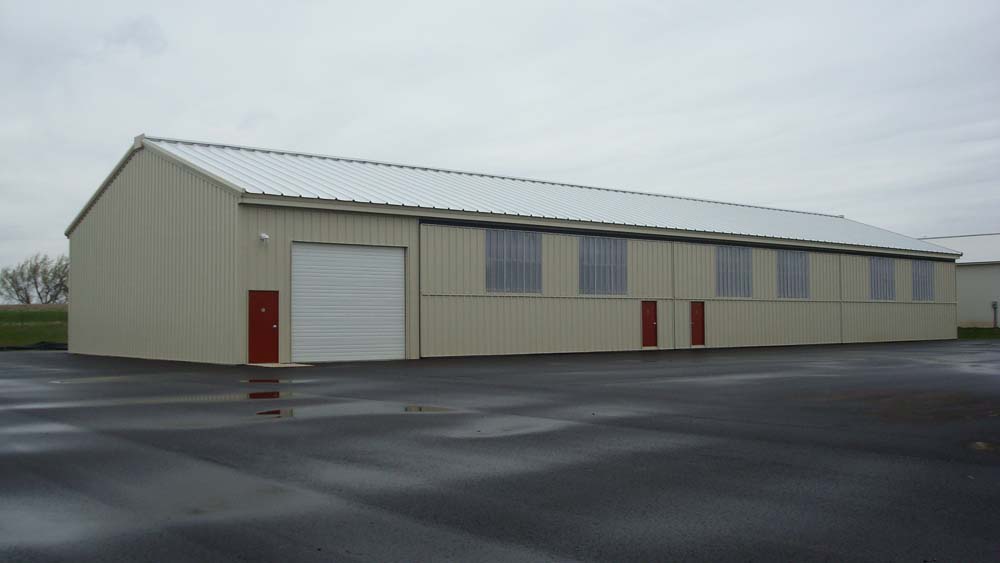
Not only do you save in building material but also the Nested T-Hangar design requires less taxiway length than our Standard T-Hangar. Compare a 10 unit N51-42 to a S36-42. The 10 unit N51-42 is approximately 100’ shorter than the comparable Standard design. That is saving over 200’ of required taxiway! By nesting the tail sections into the center of the structure, the overall length of the hangar is reduced enabling you to house the same number of aircraft.
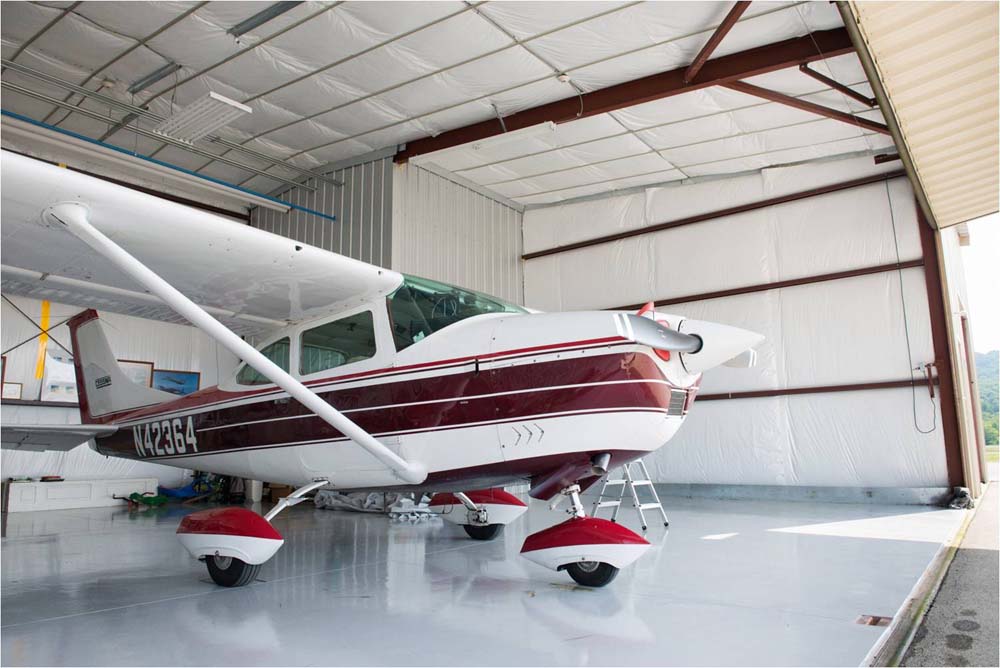
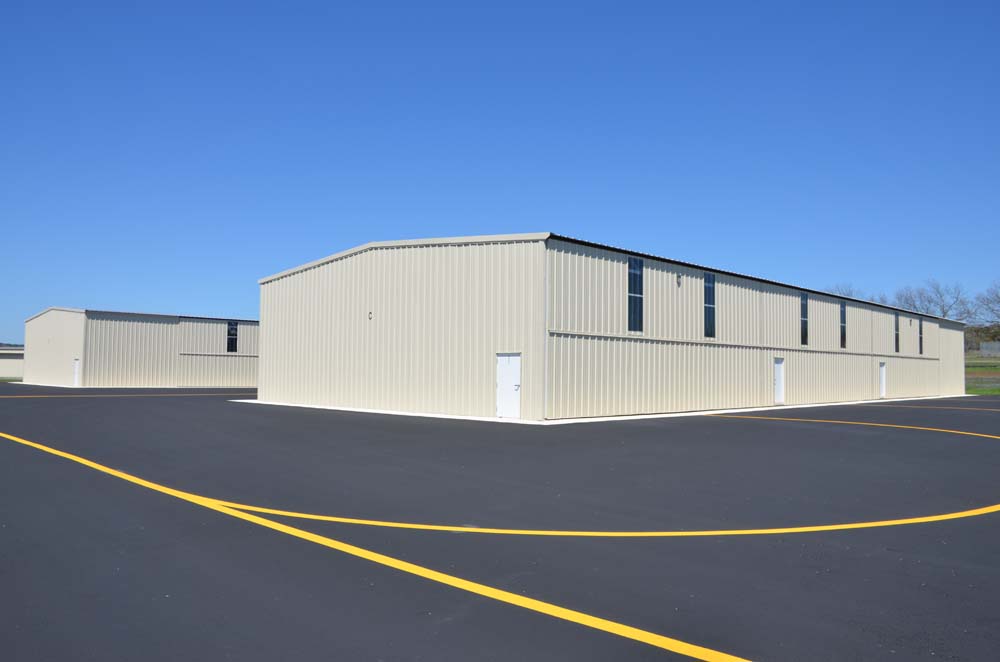
The extreme versatility of the Erect-A-Tube Nested T-Hangar design allows you to combine small and large hangars to meet individual storage requirements. It permits you to include jet pods or clear span modifications that can give you a prime opportunity to house that special aircraft with a custom hangar… all at a very reasonable cost.
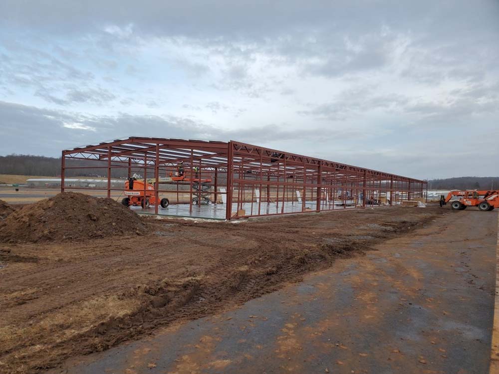
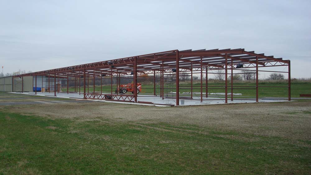
Structural frame members are precision fabricated of ASTM structural steel for strength and prefabricated for ease of erection. Unlike most hangar manufacturers who opt for “cantilever construction”, Erect-A-Tube T-Hangars are “post and beam” type construction.
“Post and beam” has long proven itself a superior construction design of T-Hangars – not only because it creates a stronger, more durable structure with more equal distribution of roof loads, allowing maximum flexibility for a variety of models.
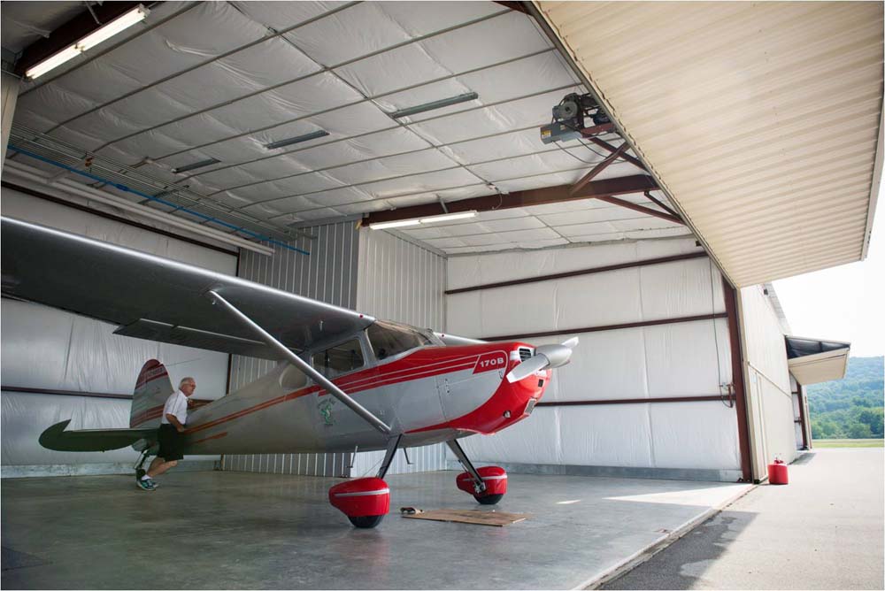
We employ a steel open web truss over the door opening on our hangars as the main component that separates Erect-A-Tube from its competitors. We advocate bridging the door openings, supporting the door, and attaching the roof instead of supporting the roof and attaching the door. After all, that is what a T-Hangar is – a series of doors with a roof over it. This exclusive feature accommodates the major load of the whole hangar and door system and provides the mounting for the door operator, sheaves and other pertinent appurtenances necessary for smooth, safe, and continuous door operation. And, when equipped with a sturdy Erect-A-Tube bi-fold door system, which in its closed position literally forms a “solid outside wall”.
|
Overall Length “B” …………………Individual Unit Dimension |
||||||||||
|
Model Number |
Width A |
2Unit | 4Unit | 6Unit | 8Unit | 10Unit |
Clear Door |
Depth |
Wing Depth |
Tail Width |
| N51-42 | 51’0″ | 63’0″ | 105’0″ | 147’0″ | 189’0″ | 231’0″ | 41’6″x12’0″ | 33’0″ | 18’0″ | 21’0″ |
| N54-42 | 54’0″ | 63’0″ | 105’0″ | 147’0″ | 189’0″ | 231’0″ | 41’6″x12’0″ | 33’0″ | 21’0″ | 21’0″ |
| N60-45 | 60’0″ | 67’6″ | 112’6″ | 157’6″ | 202’6″ | 247’6″ | 44’6″x14’0″ | 39’0″ | 21’0″ | 22’6″ |
| N60-48 | 60’0″ | 72’0″ | 120’0″ | 168’0″ | 216’0″ | 264’0″ | 47’6″x14’0″ | 39’0″ | 21’0″ | 24’0″ |
| N72-60 | 72’0″ | 90’0″ | 159’0″ | 210’0″ | 270’0″ | 330’0″ | 59’6″x18’0″ | 48’0″ | 24’0″ | 30’0″ |
NOTES:
- Dimensions above are Center Line to Center Line of columns
- Add 1’1” to center line dimensions for out-to-out concrete
- Manual Rolling Doors available for all models, in lieu of Erect-A-Tube, Inc. electric bi-fold doors